How to create a command-based robot program? There are two ways: start with the Command Robot template or use RobotBuilder.
RobotBuilder is a tool provided with WPILib for constructing robot programs conforming to the command-based application architecture. This is a tool you use when first start constructing your program. It also provides round trip engineering, which means you can switch back and forth between RobotBuilder and Visual Studio Code. RobotBuilder has a number of advantages over using the Command Robot template built into Visual Studio Code:
- RobotBuilder forces a top-down approach design approach. You first map out the high-level structures before diving into specific code.
- It generates a correct command-based structure. When building from the template, there is some risk of getting the concepts wrong.
- RobotBuilder is fast, so you watch the construction of a full program over just an hour. This would allow every programmer to write their own program for experimentation. It becomes plausible to create multiple robot programs and throw away the ones that aren’t prefect.
RobotBuilder just creates the infrastructure, so there will still be plenty of work for the programmers. It gets you started. By the end of the season, most of your code will be non-RobotBuilder code.
The following discusses deploying in Java, but C++ robot programs can be constructed in the same way.

Starting a RobotBuilder Project
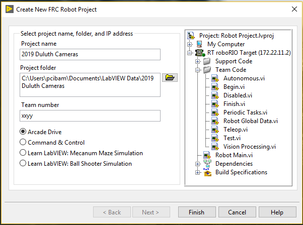
You can start RobotBuilder from within Visual Studio Code. Open the Command Palette menu by hitting control-shift-P (or command-shift-P on a Macintosh). Select “WPILib: Start Tool”. A new menu of all the WPILib tools will appear. Select “RobotBuilder”. If you have previously used RobotBuilder, it will open directly into your most recent project. If this is your first time, you will get a dialog asking your project name and team number.
When you first start a project, I recommend you do the following steps first:
- Click on the Export Directory. A file dialog will pop up to define which folder your project will be saved into. Specify that you want to “Use Absolute Path”. Select your Documents folder and hit the “Select Folder” button.
- Under the Export menu, select Java. This will cause a new project folder to be created in your Documents folder.
- Under the File menu, select Save. A file dialog will pop up. Navigate to your documents Directory and then into your new project folder. Save your RobotBuilder config file as “robot.yml”.
- Click on the Export Directory again. Change the dialog to “Use path relative”, and then select the Documents directory again.
- Click on Wiring File Location, which pops up another file dialog. Navigate to your Documents directory, select your project folder, and click the “Select Folder” button.
- Under the File menu, select Save again.
The above procedure will cause all file paths relative to the RobotBuilder save file. This will allow the project to work properly even if it is copied to another computer, or is cloned from git.
Naming Conventions
When you name things within RobotBuilder, you will be creating class names and variables in your code. You’ll want to pick names that work with your language’s naming conventions.
- Subsystems will be classes, so they should start with a capital letter. It’s a good practice if the name ends in the word “Subsystem”. For example,
ClimberSubsystemorShooterSubsystem. - Commands will also be classes, so they should also start with a capital letter. A good practice is to end all command names with the word “Command” and begin command names with the primary subsystem. For example,
ClimberUpCommandorShooterShootCommand. - Other components within RobotBuilder will be variables, so they should start with a lower case letter. RobotBuilder will allow you to put spaces in names, but this is a bad practice; don’t do it. Make variables clear about what they represent. For example,
leftClimberSolenoidorshooterMotororforwardRangefinder.
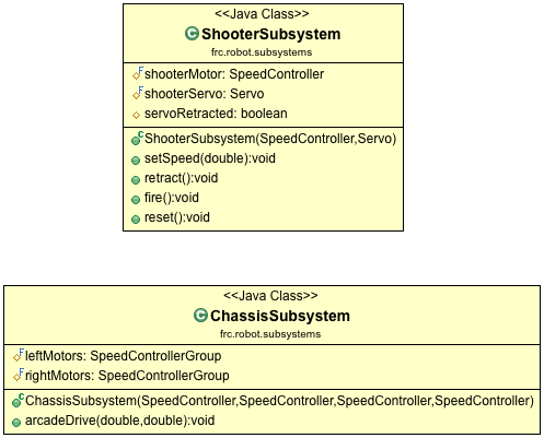
Subsystems
Suppose that your new robot has a subsystem for shooting balls using a spinning wheel. This subsystem has a SparkMax motor controller attached to PWM channel 1. The subsystem also has a pneumatic piston for pushing balls into the wheel. The piston is operated by a double solenoid connected to channels 6 and 7 of a CTRE pneumatics control module. To create a subsystem class in code:
- Right-click on the Subsystems folder and select “Add Subsystem”. This will create a new folder under Subsytems.
- Click on the new folder to select it. Change its name to ShooterSubsystem.
- Right-click on the new ShooterSubsystem folder and select “Add Actuators” and then “Add Motor Controller”. This will create a new icon for the motor controller.
- Click on the new motor controller icon. Change its name to shooterWheelMotor. Change the motor controller type to PWMSparkMax and then set its output channel to 1.
- Right-click on the new ShooterSubsystem folder again and select “Add Pneumatics” and then “Add Double Solenoid”.
- Click on the new solenoid icon. Change its name to ballPusherSolenoid. Set forward channel to 6 and its reverse channel to 7. Make sure the module type is CTREPCM.
- Under the File menu select “Save”. Under Export menu select “Java”.

At this point you have a command-based robot program with one subsystem. You can go back to Visual Studio Code and open the new folder for your project. Take a look at the new ShooterSubsystem class. You’ll see private variables pointing to the motor controller and the solenoid.
At the bottom of the ShooterSubsystem class, add these three methods:
    public void setWheelSpeed(double speed) {
        shooterWheelMotor.set(speed);
    }

    public void pushBall() {
        ballPusherSolenoid.set(DoubleSolenoid.Value.kForward);
    }

    public void retractPiston() {
        ballPusherSolenoid.set(DoubleSolenoid.Value.kReverse);
    }
These three methods will allow outside access to the private components inside ShooterSubsystem.
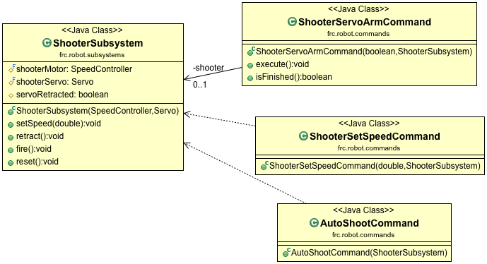
Commands
Go back to RobotBuilder. Create a method for setting the spinning wheel speed.
- Right-click on the Commands folder and select “Add Command”.
- Click on the new command icon. Change the command’s name to “ShooterSpinCommand”.
- Specify that this new command requires the ShooterSubsystem.
- Add a new parameter named “speed” of type “double”.
- Save everything and then export java code again.

Go back into Visual Studio Code and open the new ShooterSpinCommand class. Change the isFinished method so it always returns true. Then change the initialize method so it looks like this:
    @Override
    public void initialize() {
        m_shooterSubsystem.setWheelSpeed(m_speed);
    }
Next in RobotBuilder, create a command to extend the ball pusher piston:
- Right-click on the Commands folder and select “Add Command”.
- Click on the new command icon. Change the command’s name to “ShooterPushCommand”.
- Specify that this new command requires the ShooterSubsystem.
Now, repeat these three steps for a ShooterRetractCommand. Save and Export.
Switch to Visual Studio Code and open the two new commands. For both of them, the isFinished method should return true. For each of them, modify the initialize method to call the appropriate method within the ShooterSubsystem.
Operator Interfaces
Now we can create buttons to start the commands:
- Right-click on the Operator Interface folder and select “Add Xbox Controller”. Click on the new icon and rename it to just “xbox”.
- Right-click on the new “xbox” folder and choose “Add Xbox Button”. Click on the new button icon and rename it to “shooterPushButton”. Specify button “Y” and then specify the ShooterPushCommand.
- Add another XBox Button. Click on the new button icon and rename it to “shooterRetractButton”. Specify button “A” and then specify the ShooterRetractCommand.
- Add another XBox Button. Click on the new button icon and rename it to “shooterSpinButton”. Specify button “B” and then specify the ShooterSpinCommand. Click on the parameter area and specify that the speed should be 1.0.
- Add another XBox Button. Click on the new button icon and rename it to “shooterStopButton”. Specify button “X” and then specify the ShooterSpinCommand. You don’t have to specify a speed parameter for this button, since the default value is zero.
- Save and Export code.

You can return to Visual Studio Code and examine all the button setup within the RobotContainer class.
Cleanup of RobotBuilder code
There are a couple of frustrations you will encounter using RobotBuilder.
- The code is often not indented correctly. You should use the auto formatter in Visual Studio Code to correct this.
- The code is filled with messy comments which help implement the round trip engineering.
- The round trip engineering will usually break down as programmers add their own classes, or delete classes or rename things.
Although RobotBuilder will get you started, you probably won’t use it for the full season. So, a good practice is to clean up the code after a week or two of development. Auto format each class. Delete all the messy comments. Clean out the unused import statements. Make it beautiful, because code should be easy to read.
RobotBuilder Extensions
One problem you might have already noticed is that RobotBuilder might not contain all the components you want to use on your robot. In particular, you might notice that motor controls from REV Robotics or CTRE are missing. Fortunately RobotBuilder allows extensions to be added for missing parts. These extension files should be put into a folder called RobotBuilder/extensions under your wpilib directory.

One source of extensions is at https://github.com/firstmncsa/Robotbuilder-Extensions.git. Clone this repository and the drag the files into your extensions folder.
You may also need to add 3rd party extension files into the vendordeps folder of your project. You can do this from with Visual Studio Code by opening the Command Palette and selecting Manage Vendor Libraries / Install New Libraries Offline. The vendor library URLs change every year, but for 2023 they are:
- RevRobotics: https://software-metadata.revrobotics.com/REVLib-2023.json
- CTRE : https://maven.ctr-electronics.com/release/com/ctre/phoenix/Phoenix5-frc2023-latest.json
- NavX : https://dev.studica.com/releases/2023/NavX.json
Further Reading:
- The official WPILib documentation on RobotBuilder
- Brad Miller’s RobotBuilder videos:
Overview of RobotBuilder
Defining the robot subsystems
Robot Test Mode
Creating simple commands
Creating advanced commands
Create commands for driving the robot
Connect commands to the OI - Github repository of RobotBuilder extensions